|
So now we have the state of our three digital inputs and
one analog value constantly and automaticly updated inside Mach3 at
100mS intervals. Mach3 is also updating the three
outputs on the CUBLOC every 200mS. But now what....it
isn't really doing anything yet. The last piece of the
pussle will be handled by a piece of logic inside Mach3
called a BRAIN. A BRAIN is kind of like a small PLC
program running inside of Mach3. There are some good
video tutorials about BRAINS on the Machsupport video
support site so I won't go into too much details here,
just show you how to use what we've set up on the
CUBLOC.
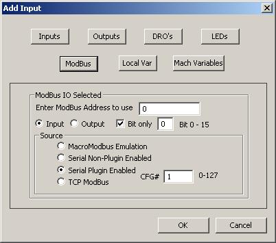
Here's a screenshot of how to setup the
input to the BRAIN to get input P5 on the CUBLOC.
Remember that we are using the Modbus Plugin and reading
P5, P6 and P7 into Modbus Cfg#1. So P5 is available at
Cfg#1 - adress 0, P6 at Cfg#1 - adress 1
and so on.
Since we really just want to pass this
signal thru to the Cycle Start function of Mach3
we add a No Operation command and then terminates
it to Cycle Start. (Make sure to watch the videos
if you don't know what I'm talking about here).
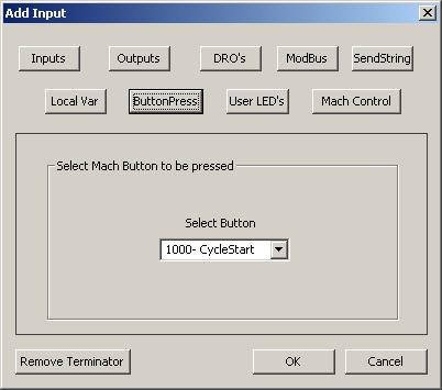
This screenshot shows the termination
dialog of the BRAIN editor. Basicly what we are doing is
"pushing" the CycleStart button with our MODBUS
input. As you can see I've selected ButtonPress
and then selected the CycleStart button in the
dropdown list.
The two remaining buttons, Feedhold
and Stop are added to the BRAIN in the same way.
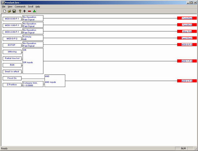
And with all three buttons added it should look
something like this:
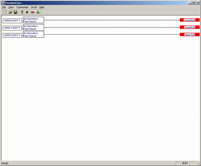
Now when we press the button connected to
P5 we activate Cycle Start. P6 activates
Feedhold and P7 Stop - COOL.
The Feedrate overide is almost as simple
as the buttons. The value from the pot comes into Cfg#2
and since we are reading one value only it has to be at
adress 0. But since the CUBLOC has a 10bit ADC
the value ranges from 0 to 1023 and a feedrate override
of 1023% is probably a little too much so we have to scale it
down some. Obviously this can be done in the CUBLOC
before the value is sent to Mach3 but we are going to do
it inside the BRAIN.
First we add the input, just as with the
buttons but Adress 0 of Cfg#2 but this
time we don't tick the Bit Only checkbox since we want
the whole value and not just a single bit. Then, instead
of the No Operation we select Formula.
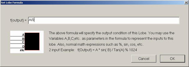
Our input value range is
between 0 and 1023. If we divide that by 9 we have a
value ranging from 0 to 113 - that's pretty good for
feedrate override.
The last thing to do for the
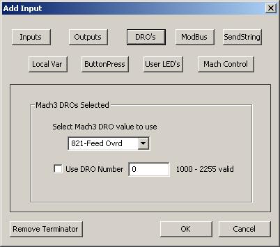
FRO pot is to send our scaled value to the
feedrate override DRO. Add a termination to the lobe,
click DRO's and select DRO 821-Feed Ovrd.
Finally let's look at the outputs. Let's
say we want one output to reflect the E-stop state of
Mach3. The second output should show if a program is
running and the last one will be used to turn on our
coolant but ONLY when the Z-axis below 0. (Not really a
pendant function but it serves the purpose of this
document...)
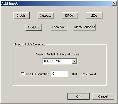 We
start by adding an input to our brain but this time we
select the LEDs button instead of MODBUS. We
start by adding an input to our brain but this time we
select the LEDs button instead of MODBUS.
In the dropdown list of available LEDs we
select number 19-ESTOP. This LED is ON when Mach3
is in E-stop mode - exactly what we are looking for.
Since the LED directly reflects the
state we are intersted in we don't have to do any
further processing so we add a No Operation and
finally we terminate the lobe to a MODBUS output. Our
outputs are in Cfg#0 and we want the first output
so we enter adress 0.
The second one is alot
trickier due to the internal complexities of Mach3.
There's no real fire proof way to be SURE if a program
is running but we have a few signals we can use to bring
us quite close to catching all circumstances.
Let's add a couple of new
inputs, 999-IsMoving, 111-Partial Line Holding,
804-RUN, & 813-Dwell In Effect. Now OR all
four together by selecting them all and adding an "OR-gate".
Finally terminate the lobe to MODBUS Output, Cfg#0
Adress 1.
Now, even with these four
signal OR'd there ARE circumstances that may make the
output go OFF even though a program is "active". One of
these are if you press feedhold and the machine happens
to hold exactly at the end of a G-code line.
The last output should be
ON when coolant is turned on but ONLY if Z is below 0.
So the first input we need is the LED telling us if
coolant is requsted, LED 13-Flood On seems like a
good fit for that. Next we need to know if the Z-axis is
below 0 so we add DRO 804-Z Position as an input
too. Select the Z-position "input" and add a compare
lobe to it - Compare Immediate Less than 0.
Now select the Flood On
lobe and the Compare Imm lobe and AND them
together with a 2-input AND lobe. Finally
terminate it to MODBUS output Cfg#0 Adress 2.
By now your complete brain should look something
like this:
Hopefully it works too. In
Mach3 select Operator/Brain Control and click
Reload all Brains. Then select the previously
created Brain and enable it. If you want you can view it
as it runs by clicking the View Brain button.
Have fun!
/Henrik Olsson.
2007-11-01 |