|
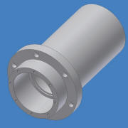
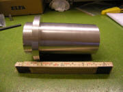
So, to the left is a
rendering of the housing for the spindle. The total
length is 190mm and the diameter is 90mm. The flange is
125mm in diamter and has 6 mounting holes for M6 screws.
I really wanted to make the housing out of some good
quallity steel but ended up making out of aluminium. In
the future I may "upgrade" to a steel housing if need be.
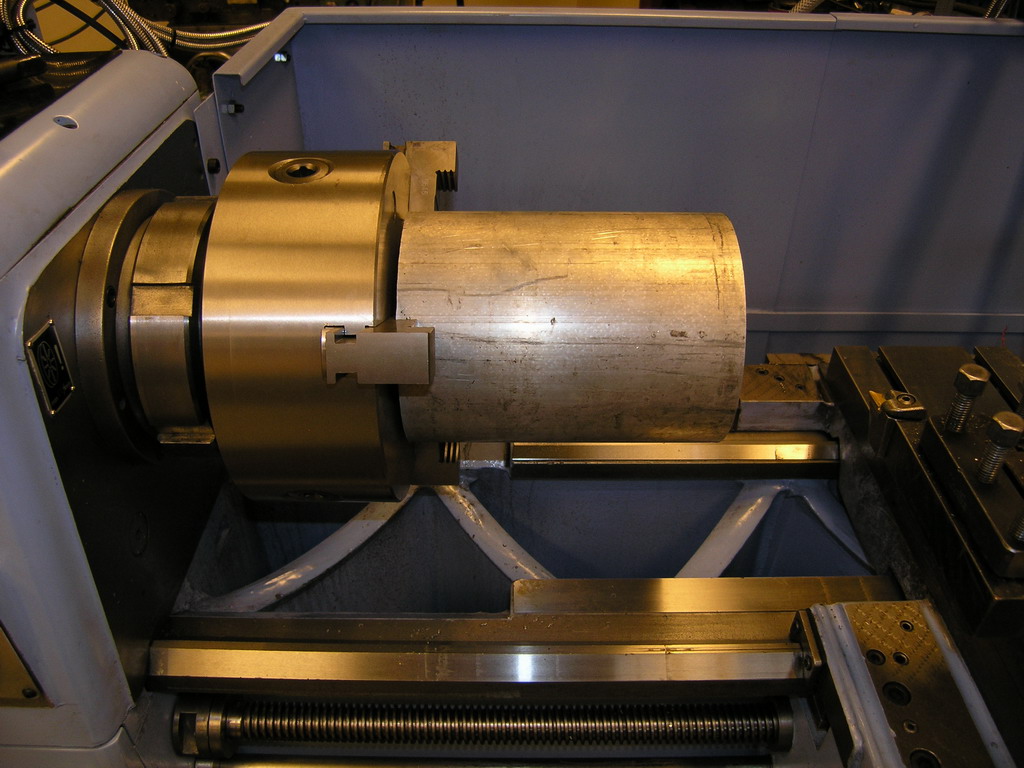
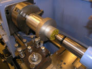
Here we are - set up
for the first operation on the housing. The stock is
160mm in diameter so there was a lot of material to
remove. The lathe is newly restored Storebro and it was
a joy to use it for this project.
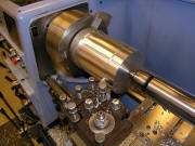
I started by squaring off
the end and then drill it with a spotdrill so that I
could use the live center. Then I started to machine
down the 160mm bar.

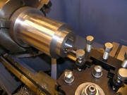
In this picture the outer
diameter of the lower part has been turned down close to
90mm and the rest close to the 125mm that OD of flange
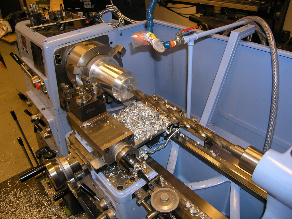
is supposed to be. I then started to work my way up thru
the drill sizes. That's quite a long drill....

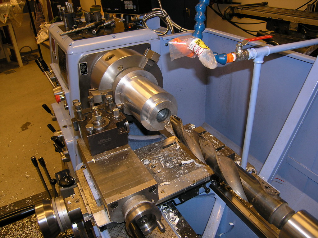
...and that's quite
a large drill.
After roughing out the ID
with the drill I started turning the bore for the lower
bearings. These bearings are 72mm in diameter and I
wanted a light press fit.
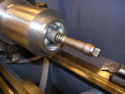
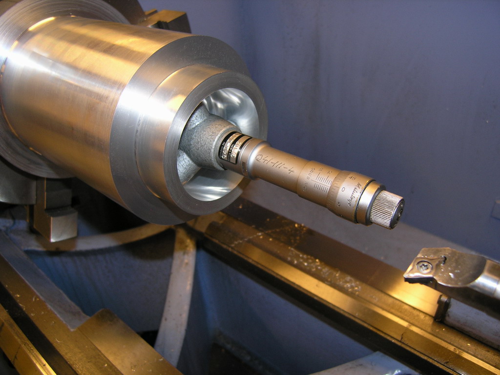
Slowly bringing it to size,
measuring with a three point micrometer between each
pass.

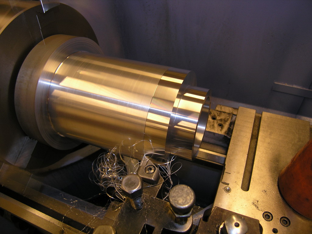
And then a final pass on
the OD to bring it to it's final dimension. Then comes
the fun part - turning it around and getting it to run
true so that the upper bearing bore could be machined
100% (or close to) true to the lower one.
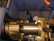
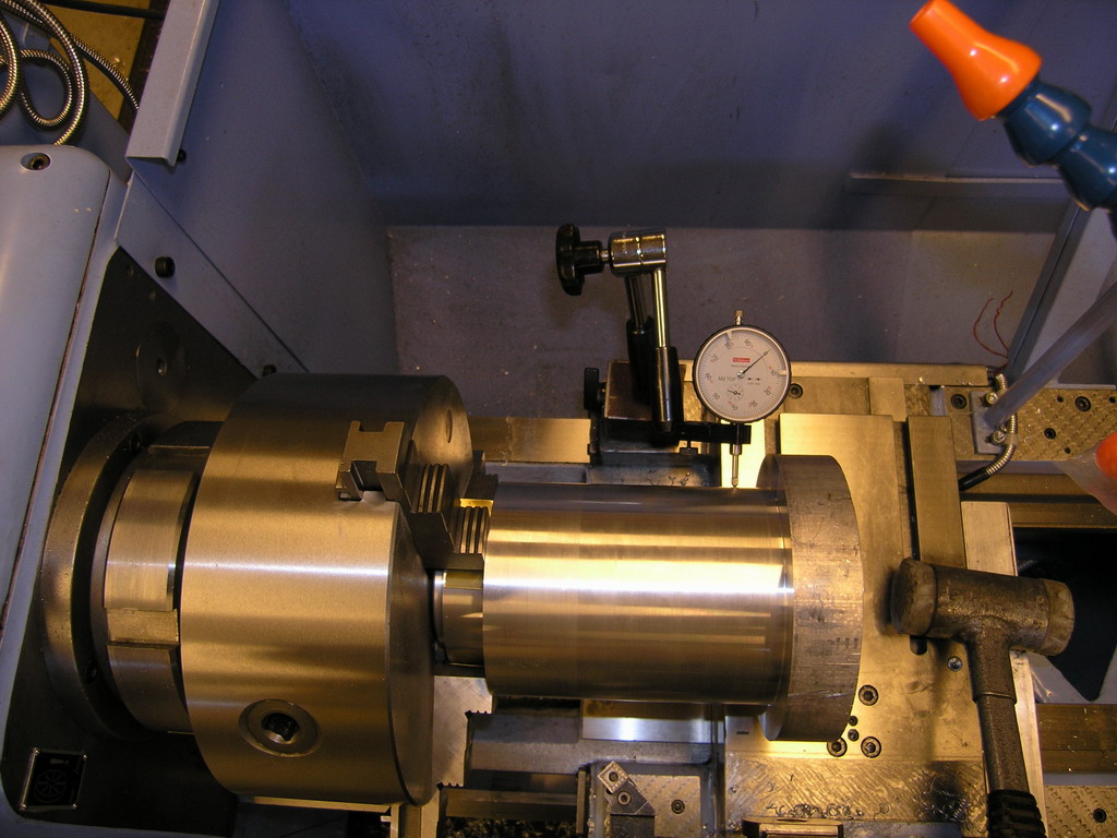
I made a "plug" that was a
close fit to the lower bearing bore and iserted it
before clamping it in the chuck. It can be seen sticking
out just a little between the jaws of the chuck. This
was obviously done so that the force from the chuck
shouldn't destroy the nice bearing bore. A dial test
indicator and a plastic hammer is used to make sure that
the housing runs true - I managed to get with in 0.01mm.
First I machined the upper
bore. When that was finished I made another "plug" since
none of the live centers I had access to was big enough
to fit the newly machined bore. Then I started to
machine down the rest of the housing to its final
dimension. When that was done I had one simple operation
left and that when it happened. I wanted to take a light
cut on the upper end but to able to do that I had to
remove the "plug". And when taking that last cut the
whole housing came loose from the chuck, resulting in
some really uggly dents and one really scared operator (me).
A rotary table was then
set up in the mill and mounting holes as well as the
tapped holes for the flange was drilled and tapped. (Sorry,
no photos of that op.)
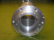
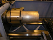
These two last photos
shows the finished housing. You can clearly see the
marks from "crash" in the second photo. Hopefully it's
just cosmetic and the housing is still straight with
round bores for the bearings but only time will tell. If
it IS messed up I will make a new one.
<BACK> <NEXT>
|