|

In parallel with the mechanical construction of the
machine I started building the electronic cabinet. The
main parts are:
- 3 G210 Stepmotor drives.
- 45V DC Main powersupply roughly 500VA
- 24V DC Powersupply for auxillary function
- Relay circuit for power and E-Stop condition
- Opto isolation for signals from machine to PC.
(Home / Limits etc)
- Chargpump safety circuit. In line with E-Stop
loop.
- Isolated F/V converter for spindle VFD.
- Auxillary relays for coolant or whatever.

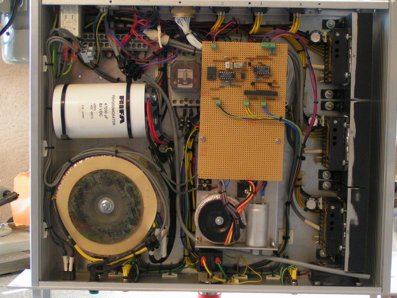
In the left section of this photo you can see the
main power supply with it's transformer, rectifier and
capacitor. The middle section shows the V/F converter
for the VFD and the auxillary power supply The cards
for the opto isolation, chargepump safety circuit and auxillary relays
are hidden below the auxillary powersupply. The right
section of the box contains the three stepmotor drives
mounted on heatsinks. The relay between the
capacitor and the circuit board is the main power supply
contactor. This turns off the 220V AC to the main
transformer whenever there's an E-Stop condition.
I'm not too satisfied with the look of the inside of
this thing but it wasn't supposed to be this much stuff
in it from the beginning. There is a little space left
on the vero board for the V/F converter but other than
that the box is pretty much full to the limit.
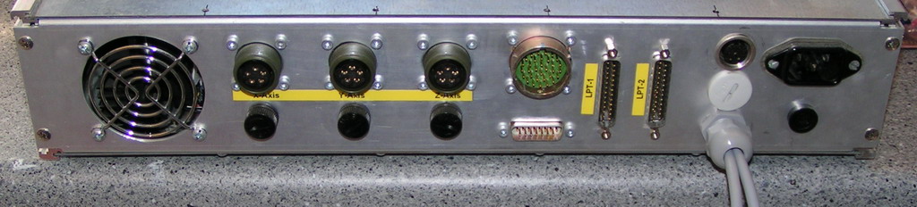
Here's a shot of the back of the box.
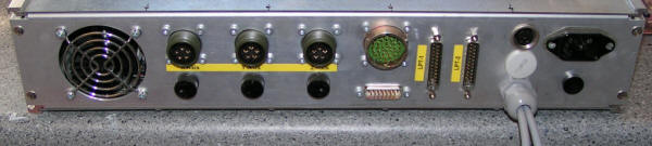
Starting from the left we have the motor outputs
and it's corresponding fuse. Then there's the connector
for the external I/O (homeswitches and such) this connects to
a box on the back of the machine where the cables for
the homeswitches etc are connected.
Below it there's the DB15 connector which is used to
supply 5V from the computer to the G210's. To the right
we have the two parallell port connectors which of only
one is used at the moment. Then there's the
connector for the VFD, carrying On/Off- direction- and
frequency signals. There's also two extra connectors for
the E-stop loop (the gray cables). One is for the E-stop
button on the control panel and the other one is not yet
implemented.. To the far right we have the power inlet/filter
and it's fuse.
You can download schematics for this box
here. (Right click, save target as)
<BACK>
<NEXT>
|